The author is director, RF engineering at Shively Labs.
We all want to get the most value out of money spent.
RF system repair can be costly. However, a well-implemented maintenance program can greatly reduce the need for repairs — and when there is damage or degradation to a system, that program can detect and address the issue early, when repair costs are low.
One very useful tool in RF system maintenance is baseline measurements.
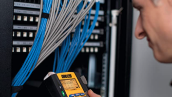
Taken at the time of acquisition or system commissioning, these provide a snapshot of the condition of the RF system. They can then be compared to later measurements and reveal trends in performance.
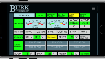
These measurements might include transmission line sweeps, transmitter operating parameters, forward and reflected power samples, thermal readings of filters, transmission line and connections, current and resistance measurements of deicer systems, RF spectrum measurements, pressurization and signal coverage.
The hardware between the transmitter output and the antenna radiator is the final stage of the FM transmission system. This part of the transmission system can contain RF switches; directional couplers; elbow complexes; band-pass, band-stop and notch filters; long transmission line runs; power splitters; “T”s; matching networks; feeder cables, etc.
It’s crucial to the delivery of signal to your coverage area to take the time to get this section right and then keep it right.
During antenna installation, the tower crew and site manager rely on manufacturers to show clearly the antenna position and orientation on the tower.
I’ve seen this exchange break down, resulting in antenna parasitic elements mounted in the wrong position, causing both high VSWR and poor coverage. Fortunately, it was a quick fix to correct the VSWR and signal coverage. Unfortunately, it required a tower crew and two engineers to visit the site.
If care is taken with the details during installation and the system is optimized, it’s at its best and should provide years of service.
(I left the “trouble free” part out intentionally. RF system maintenance … what can break? It’s just bent pieces of metal, right?)
Proactive mindset
Just about anything can happen to cause failure in an RF system.
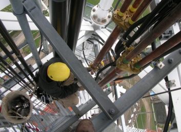
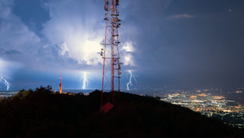
Antenna damage from wind, falling ice, lightning, tower work, vandalism, loose connections and aging components are just a few. When an engineer has multiple systems to take care of, something always seems to be in need of attention.
One way we have some control over such failures is regular system maintenance.
Have you ever checked site parameters after a significant weather event and found that some parameter had changed — not to the point of failure, but enough to prompt an investigation? Then upon a closer look you found damage that needed repair?
Or perhaps on a routine site visit, you discovered excessive heat on one or more components, and upon further investigation found an elbow that was nearly kaput — it would have failed catastrophically within weeks or days.
This is proactive maintenance and repair. If these near-misses haven’t happened to you, they likely will.
Had you been unable to check those readings after that storm and thus could not notice increasing VSWR, or had you not visited that site and noticed the hot elbow, the condition would have persisted, worsened and eventually failed, taking your station off the air.
That call usually comes at midnight on Super Bowl weekend.
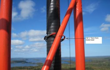
Checking sites that have suffered through extreme weather events is a prudent practice. So are regular visits, even to sites that may be considered trouble-free. The periodicity will vary — more frequent for trouble sites, perhaps quarterly or even semiannually for more reliable sites.
Annual tower climbs are great if it’s in the budget, but when they are not possible, we come back to intimate knowledge of system performance and those baselines, and running history logs that allow us to review for any indication that a problem has started and at what rate it is changing.
This can be useful information when determining if you need to scramble to make a maintenance visit immediately or can schedule for a later date.
Sample issues
Some things to look for when inspecting for damage in the antenna:
- Loss of dry air pressure, whether entirely or through a slow leak.
- Missing or damaged radiators. Pay close attention to the ends of the radiator and the feed points.
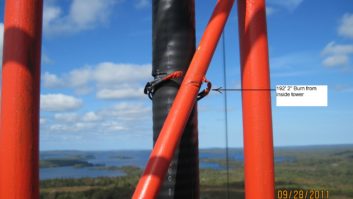
- Kinked, compressed or burned cables.
- Broken or unsealed radomes and/or plugged drains that cause water to collect.
- Parasitic elements in place and undamaged.
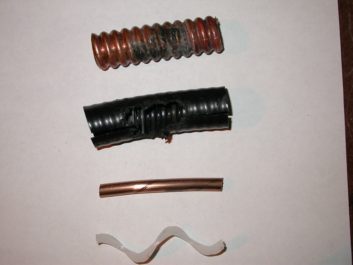
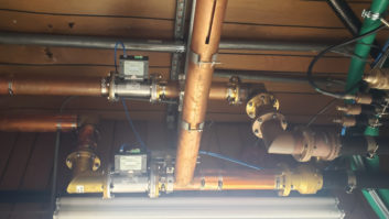
In more complex systems, the power dividers and coaxial lines should be installed without undue mechanical stress on the components.
The coax should have the appropriate hangers and fasteners where they cross tower members or other antenna feed components. Consult the manufacturer for specific recommendations and best practices.
Antennas that have deicers systems usually have an external wiring harness to distribute AC power to each heating element within each radiator. The manufacturer will have the resistive values for each element and current draw to expect.
An ammeter measurement of each leg of the circuit, including the neutral, will give the first clues to the condition of the deicer system.
If the wiring harness was not installed correctly or fasteners have fallen away over time, the harness can hang in the high RF environment. This can cause reflected power issues at the transmitter and changes in coverage; it can cause currents to be induced into the wiring harness, and voltages large enough to cause arcing between the conductors of the wiring harness and tower members or other cables that pass in close proximity.
Visual documentation
Finally, take lots of photos, photos, photos.
This is a great way to document how the antenna was installed and its current state. When you share photographs with the antenna manufacturer, they have very useful information to inform their recommendations.
With a single-radiator antenna it will be obvious when something is not quite right. On panel antennas, the multiple bays, multiple radiators per bay and numerous feeder cables can really mask a problem.
This brings to mind a recent incident where a station engineer noticed a slight increase in VSWR from 1.05 to 1.15. This occurred right after a tower crew had been working above the antenna, removing old TV equipment.
The engineer noticed the change and hired a crew to climb and inspect the antenna. They found that a cable had been caught at some point during the rigging and pulled sideways until it caused a severe kink at the point where it attached to the radiator input.
If the indications had not been heeded and the cable replaced, the next indication would have been loss of pressure, resulting from a coax burn. And we know what happens when we let the magic smoke out.
Ultimately, having an intimate knowledge of your system’s performance, both within the RF system and in the coverage area, will serve you well. This knowledge will allow you to prioritize your maintenance schedule by need, effecting maintenance to correct small problems before they become big expensive ones.
