In the Aug. 10 issue, we wrote about the centennial of condenser microphones. Let’s look more closely at electret condenser microphones.
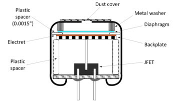
These self-charged microphones number in the billions — hiding in just about every consumer audio device from cell phones to speech-enabled appliances. Electret condenser elements also are used in professional-quality microphones, the subject of this article.
Items covered include:
• How can an element so small be directional over a wide frequency range?
• What determines the frequency response of a directional electret microphone?
• Why do some microphones produce a bass boost at close distances from the source?
This discussion gives some explanation of the physics behind these phenomena, rather than just saying “things happen” (as some microphone basics seem to do). The math may be a little dry, but I hope the answers are of interest and clear up some performance characteristics of this class of microphones.
Sizes of electret condenser microphone elements
When considering their size, performance and cost, electret condenser microphones are one of the wonders of electromechanical manufacturing. As shown again in Fig. 1, only a few components are needed:
• An ultra-thin sheet of plastic, metalized by vapor deposition (the diaphragm)
• An electrostatically-charged sheet of plastic (the backplate in a back-electret microphone)
• A pressed-metal cylinder (the case)
• Conductive and insulating washers or spacers
• A Junction Field Effect Transistor as impedance-converter (optional, but almost universal)
These few components can be manufactured cheaply. JLI Electronics (www.jlielectronics.com) sells capsules in single quantity for under a dollar.
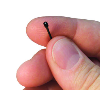
Because of their simplicity, the capsules can be shrunk in size for almost any device. An extreme example is the Countryman Associates model B6 microphone seen in Fig. 2, which is only 2.5 mm (0.1 inch) in diameter. Thanks to its electret design, the size makes it almost invisible for the earsets worn by stage performers. Despite its vanishing size, the B6 has an almost ruler-flat frequency response from 20 Hz to 20 kHz, low noise and sensitivity comparable to large microphones.
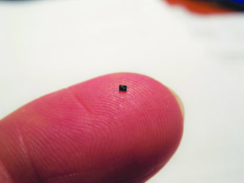
Electret condenser microphones the size of the Countryman B6 have been a common part of cellphones — at least until recently. Electret devices were the natural choice for manufacturers as cellphones shank in size. The impedance converter and amplifier to go with the electret microphone had to shrink, too. The current size is illustrated by the Texas Instruments LMV1012 microphone preamplifier, shown in Fig. 3 on the author’s finger. This IC contains a high-performance amplifier designed to replace the JFET and amplifier, with a gain of up to 24 dB, an A-weighted noise of –89 dBV and THD of 0.09 percent. A few were ordered for experimentation before I realized that a “4-bump DSBGA (die-size ball grid array)” package is approximately one square millimeter (0.0016 square inches). Needless to say, connecting this device with regular tools is impossible!
For cellphones and such, a successor to the electret condenser microphone has taken hold that relies on microelectromechanical systems (MEMS) manufacturing. MEMS is a combination of microscopic processing by chemical deposition, lithography and electrochemical etching. MEMS microphones integrate the electronics onto the silicon chip, and are unique ICs in that they have a tiny hole in the top for the sound to reach the pressure-sensitive membrane.
While exceedingly small and thin, MEMS microphones share a great deal with electret microphones, because the membrane acts as a variable capacitor with a fixed backplate. As sound pressure deflects the membrane, a change in capacitance results, causing voltage change.
An example of a MEMS microphone is the ADMP421, a high-performance, low-power, bottom-ported omnidirectional MEMS microphone that is approximately 2.7 mm by 3.5 mm (0.015 square inches). Its electronics include a fourth-order Sigma-Delta digital converter to provide digital-output to other parts of the mobile device.
Electret microphones can range in diaphragm size, of course, and large diaphragm models, deemed to be 1 inch or larger, are made. A larger diaphragm allows larger changes in capacitance as sound waves vibrate the diaphragm in and out. This tends to generate a higher output voltage than a small diaphragm, given the same sound pressure level (SPL).
In Table 1, two capsule products (Figs. 4 and 5, in the chart) provide a rough comparison using data from the JLI Electronics website.

In viewing the table for these unidirectional (cardioid) microphones, note that the JLI-85A-T has an internal Field Effect Transistor (FET), while the TSB-25AXZ3 has no impedance converter. The FET may introduce a slight loss in output voltage, which the impedance converter for the TSB-25AXZ3 also may have, thereby reducing the 5 dB difference in output sensitivity. However, the capsule manufacturer has estimated a larger difference in signal-to-noise ratio of 8 dB, and with careful design of the amplifier, the TSB-25AXZ3’s higher signal-to-noise ratio may be maintained.
A higher signal-to-noise ratio is valuable in situations such as recording instruments at a distance from a classical music ensemble. It is not significant when miking instruments closely, and in fact large diaphragm microphones tend to have lower sound pressure overload limits.
How is directionality achieved?
As we’ve seen (and many readers have experienced), electret microphones have directional patterns despite the small size of the capsules. It is curious how such a small element can effect a directional response. After all, the speed of sound at 20°C and sea level is 343 m/s, so a wavelength at 1000 Hz is:
![]()
So how the sound around a microphone element can be discriminated by direction, when the wavelengths are far larger than the capsule? Directional electret capsules belong in one of two categories of microphones called pressure gradient transducers. These transducers produce a voltage proportional to the amplitude of the diaphragm movement or excursion.
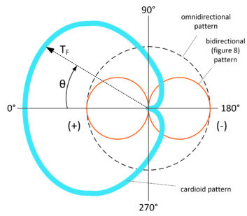
If these microphones have equal sensitivity to pressure on the front and the back, they have a figure-8 directional pattern as shown by the brown circles in Fig. 6. Equal sensitivity to pressure would result if the microphone was identical on the front and back of the diaphragm. A minimum in pickup, or null, occurs at 90 degrees and 270 degrees relative to sound arriving perpendicular to the diaphragm, at 0 degrees. The field transmission factor TF (sensitivity) at any angle, θ, is:
![]()
where:
TF0 is the sound field intensity at 0° (maximum), and
θ is the angle from the perpendicular to the diaphragm.
Referring to Fig. 6, a cardioid or heart-shaped pattern (blue) results when an omnidirectional pattern (dashed circle) is added in phase and equal in gain to the front lobe of the figure-8 pattern (brown). The gain of the cardioid pattern as a function of the angle, θ, using the same terms as above, is:
![]()
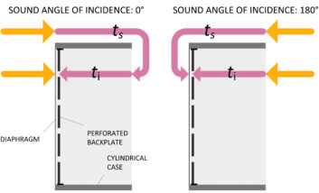
Some cardioid microphones are constructed just this way, with figure-8 and omnidirectional pressure gradient transducers. But the directional effect of small microphones, such as the omnidirectional electret condenser shown in Fig. 1, is achieved with one diaphragm by making only a couple of changes. The left side of Fig. 7 shows a simplified diagram of the principle. For the pressure wave with an angle of incidence at 0 degrees, sound arrives from the left and reaches the diaphragm. This side of the microphone can be thought of as the omnidirectional part. However, the pressure wave travels along the cylindrical microphone case and is able to reach the back of the diaphragm through perforations in the backplate (the omnidirectional microphone has a solid backplate). This bidirectional access to the diaphragm may be thought of as the figure 8 pattern. Combining these responses to pressure waves creates a cardioid response pattern, but creates a problem: tilted frequency response.
A change in amplitude response with frequency results because the pressure wave impinges on each side of the diaphragm at approximately the same intensity but with a phase difference added by the collective path, ts and t1. The addition of that path is only a matter of centimeters, and considering the speed of sound discussed above, the phase differential of the pressure on each side of the diaphragm is very small at the low end of the audible frequency range — only a degree or two. However, this phase difference increases linearly as the frequency increases. Fig. 8 illustrates the frequency response that results from the phase differential for a ts + t1 path of 15 mm. That is a canister length of about 7.5 mm (0.3 in), which is typical of many miniature electret microphones. The response rises to the phase transition frequency ft, which occurs at approximately 8.5 kHz with the first null at 2 · ft, or 17 kHz. This frequency response shifts left or right depending on the size (ts + t1 path) of the microphone.
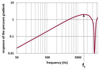
To correct the rising response, sound openings on the backplate and the rear cover of the microphone (not shown in Fig. 8) are designed as an acoustic low-pass filter. Acoustic correction has limits, which often results in gain rolloff at the low frequency end. This is evident when comparing a cardioid capsule response to a sealed omnidirectional capsule of the same size. At the high end, the notch at 2 · ft may be filled in with some rolloff in evidence. Fortunately, the process works for wavefronts from the rear, as shown on the right side of Fig. 7, and for other arrival angles around the microphone. Some variation in the frequency correction may occur, which explains why the frequency response curves vary with direction as well as the polar pattern directivity.
Why is proximity effect, and how does it happen?
As we’ve discussed, omnidirectional microphones — electret condenser and other pressure microphones — maintain their frequency response at any distance from a point source pressure wave. All directional pressure gradient microphones exhibit an increase in low-frequency response as a point source nears — a proximity effect. Referring again to Fig. 7, this occurs because the sound arriving at 0 degrees is delayed on its way to the rear face of the diaphragm by the path ts + t1. The length of ts varies with the angle of the arriving wave, reducing to a difference of t1 at 180 degrees.
Using our previous models of the virtual figure 8 and coincident omnidirectional microphones, the difference to the same place on each side of the diaphragm from a point sound source is expressed in the following, adapted from a formula by Georg Neumann GmbH:
![]()
where:
e8 is the output of a figure 8 microphone,
eO is the output of an omnidirectional microphone of the same sensitivity,
λ is the wavelength in meters, and
r is the microphone distance from a point source in meters.
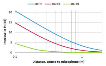
When the effect of the pressure differential on the figure 8 microphone is added to the omnidirectional microphone, a curve of the proximity effect on frequency response is produced, as shown in Fig. 9. The rise in response at 100 Hz — a frequency present in speech — could be 10 dB to 15 dB for distances of 0.1 m to 0.2 m (4 to 8 inches). The rolloff effect of cardioid microphones discussed above may tend to counteract this proximity boost at lower frequencies, resulting in an apparent “bump” in response near 100 Hz.
Some of this investigation was aided thanks to an excellent guide, “Microphones, Methods of Operation and Type Examples” by Gehart Boré and Stephan Peus of Georg Neumann GmbH, which is available on the Neumann website at neumann.com.
John Kean is a principal engineer with Cavell Mertz & Associates and has a private consulting practice for broadcast audio clients. He is former senior technologist for NPR Labs.


